Guardian Alarm System Manual: A Comprehensive Guide
This manual details the Guardian Alarm System, tracing its origins to the Manchester Guardian’s founding in 1821,
and its evolution through Guardian Savings Bank’s community focus, while distinctly separating it from gaming tools like Game Guardian.

The system’s components—CPU control board, power supply, sensors, and remote units—are thoroughly explained,
illustrated with figures detailing installation and operation, ensuring comprehensive understanding for users and technicians alike.
Welcome to the Guardian Alarm System, a robust security solution built upon a legacy of trust and reliability.
Tracing its roots back to the principles established by the Manchester Guardian in 1821 – a commitment to vigilance and public service –
our system is designed to provide unparalleled protection for your property and peace of mind.
This manual serves as a comprehensive guide, detailing every aspect of the system, from core components and installation procedures to daily operation and advanced settings.
We acknowledge the existence of entities like Guardian Savings Bank and the unrelated Game Guardian,
and clearly differentiate our security system to avoid any confusion.
Understanding the system’s functionality is paramount.
This guide will empower you to effectively arm, disarm, and respond to alarm activations, ensuring a secure environment.
We’ll cover troubleshooting common issues and performing essential maintenance, maximizing the lifespan and effectiveness of your Guardian Alarm System.

Understanding the Core Components
The Guardian Alarm System’s effectiveness relies on the seamless integration of several key components. At its heart lies the Central Processing Unit (CPU) Control Board,
the system’s brain, managing all sensor inputs and alarm outputs. This is powered by a reliable AC/DC Adaptor & Power Supply,
ensuring continuous operation even during power outages.
Temperature Activated Sensor Assemblies/Distribution Assemblies detect potential threats, triggering alarms when necessary.
Remote Alarm Units provide a convenient means of manual activation, while Manual Remote Pull Stations offer a traditional, fail-safe activation method.
Each component is meticulously designed for optimal performance and durability, reflecting the Guardian legacy of quality.
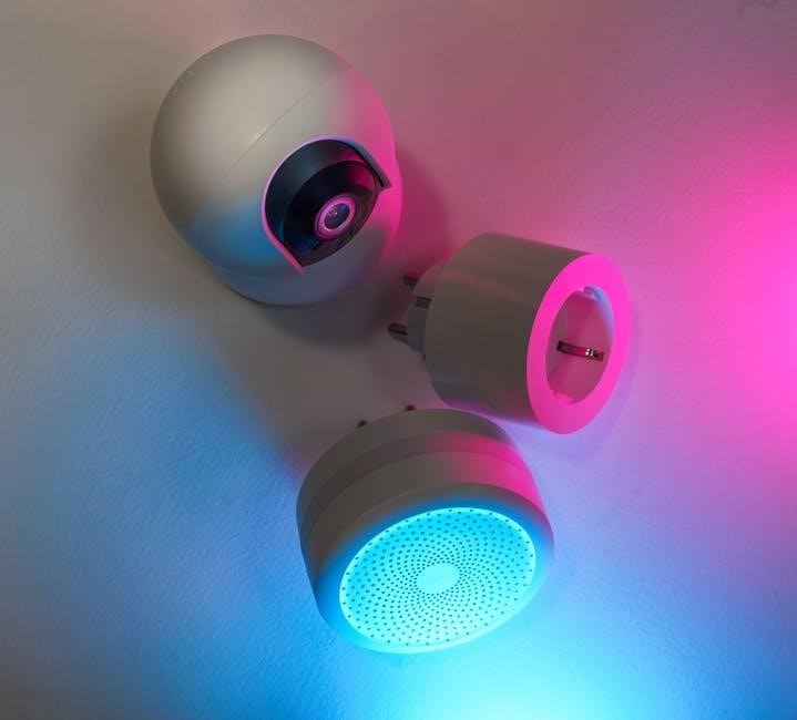
Figures 2 through 7, referenced within this manual, provide detailed visual representations of each component and their respective installation procedures.
Understanding these core elements is crucial for effective system operation and maintenance.

System Components & Functionality
The Guardian system integrates a CPU, power supply, temperature sensors, remote alarms, and pull stations,
working in concert to provide robust and reliable security, as detailed in accompanying figures.
Central Processing Unit (CPU) Control Board
The CPU Control Board serves as the central nervous system of the Guardian Alarm System, orchestrating all functions and interpreting signals from connected sensors and devices.
As depicted in Figure 3, this board is responsible for processing alarm triggers, managing system arming/disarming, and facilitating communication with remote alarm units.
It houses the core programming logic, user code management protocols, and system log storage capabilities.
The board’s internal architecture allows for customizable settings, zone configurations, and event logging for detailed analysis.
Proper functionality of the CPU is paramount for reliable system operation, requiring a stable power supply (detailed in the AC/DC Adaptor section) and correct wiring connections.
Regular system log reviews, accessible through the control panel, can reveal valuable insights into system performance and potential issues.
The CPU’s ability to differentiate between various alarm signals—temperature activation, manual pull station, or remote trigger—ensures accurate and targeted responses.
AC/DC Adaptor & Power Supply
The Guardian Alarm System relies on a robust AC/DC Adaptor (Figure 3A) to ensure uninterrupted operation, converting standard AC power into the DC voltage required by the CPU Control Board and connected sensors.
A stable power supply is critical; fluctuations can lead to false alarms or system failures. The adaptor is designed with surge protection to safeguard against electrical spikes and transient voltages.
The system incorporates a backup battery system (detailed in the Troubleshooting & Maintenance section), providing power during AC outages.
Regular battery checks and replacements are essential to maintain continuous protection. Proper grounding of the power supply is vital for safety and optimal performance.
The power supply’s capacity must align with the total power draw of all connected components, preventing overload and potential damage.
Incorrect voltage or polarity can irreparably harm the CPU Control Board, necessitating professional repair or replacement.
Temperature Activated Sensor Assembly/Distribution Assembly
The Temperature Activated Sensor Assembly (Figure 4) is a crucial element in the Guardian Alarm System, designed to detect rapid temperature increases indicative of fire. These sensors utilize heat-sensitive elements that trigger an alarm signal when a pre-defined temperature threshold is exceeded. The Distribution Assembly efficiently relays these signals to the Central Processing Unit (CPU).
Proper placement of these sensors is paramount, avoiding areas with normal temperature fluctuations (like kitchens) to minimize false alarms. Sensor assemblies are interconnected, forming a network that provides comprehensive coverage of the protected area. Regular testing, as outlined in the Maintenance section, verifies operational integrity.
The system supports multiple sensor types, allowing customization based on specific environmental needs. Careful consideration of mounting height and spacing optimizes detection capabilities, ensuring swift and reliable alarm activation in the event of a fire.
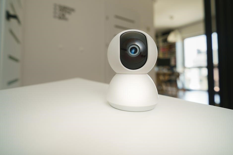
Remote Alarm Unit – Overview
The Remote Alarm Unit (Figure 5) extends the Guardian Alarm System’s reach, providing manual activation capabilities in areas distant from the main control panel. These units are strategically placed for accessibility, enabling personnel to initiate an alarm response quickly during emergencies. They are particularly useful in large facilities or areas where immediate access to the central panel is limited.
Each unit features a clearly labeled activation button, protected against accidental triggering. Upon activation, the remote unit transmits a signal to the CPU, initiating the pre-programmed alarm sequence. Installation procedures (Figure 6) emphasize secure mounting and reliable wireless communication.
Regular testing of remote units is essential to confirm functionality and battery life. The system supports multiple remote units, allowing for comprehensive coverage and enhanced safety protocols.
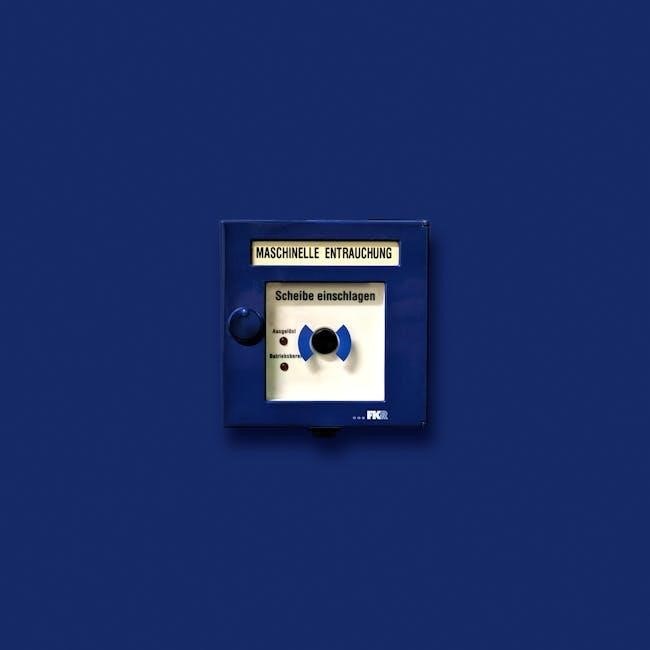
Manual Remote Pull Station – Operation
The Manual Remote Pull Station (Figure 7) serves as a critical, direct activation point within the Guardian Alarm System. Designed for immediate use in emergency situations, its operation is intentionally straightforward. To activate, firmly pull down on the clearly marked handle; this action initiates an immediate alarm signal transmission to the Central Processing Unit (CPU).
Upon activation, a visual indicator on the station confirms the alarm has been triggered. The system is designed to remain activated until manually reset by authorized personnel at the CPU control panel. Regular inspection of the pull station is crucial to ensure the handle moves freely and the visual indicator functions correctly.
Training personnel on the proper operation of the pull station is paramount for effective emergency response. Avoid obstructing access to the station and ensure clear signage is present.
Installation & Setup
Proper installation is vital for optimal performance; this section details procedures for the system enclosure, remote alarms, and sensor placement, alongside detailed wiring guides.
Installing the System Enclosure/Extinguisher Assembly
The system enclosure, often integrated with an extinguisher assembly (as depicted in FIGURE 2), requires careful mounting to ensure stability and accessibility. Select a location that is protected from accidental damage and provides clear visibility for status indicators.
Prior to mounting, verify the wall’s structural integrity to support the combined weight of the enclosure and any integrated extinguishing agent. Use appropriate anchors and fasteners suitable for the wall material. Ensure the enclosure is level to prevent operational issues.
Connect the power supply and any auxiliary wiring according to the wiring diagram (detailed in a later section). Double-check all connections before powering on the system. Finally, secure the enclosure door with the provided locking mechanism to prevent unauthorized access and tampering.
Remote Alarm Installation Procedures
Remote alarm units (FIGURE 5 & 6) extend the system’s coverage to areas distant from the central control panel. Begin by selecting strategic locations, considering potential hazards and accessibility for activation. Mount the unit securely to a wall or post, ensuring it’s within range of the CPU.
Run low-voltage wiring from the control panel to the remote alarm, adhering to local electrical codes. Utilize shielded cabling to minimize interference. Connect the wiring to the designated terminals on both the control panel and the remote unit, verifying polarity.
Test the remote alarm functionality after installation, initiating a signal to confirm communication with the CPU. Document the remote alarm’s location and ID for accurate event logging and response.
Sensor Placement & Optimization
Optimal sensor placement (FIGURE 4) is crucial for reliable detection. Temperature-activated sensors should be positioned in areas prone to rapid temperature increases, avoiding direct sunlight or heat sources that could cause false alarms. Consider air circulation patterns to ensure effective coverage.
For comprehensive protection, strategically locate sensors to cover potential entry points and critical areas. Avoid obstructions that could block the sensor’s field of view. Regularly inspect sensor lenses for dust or debris, as these can impair performance.
Calibration is key; adjust sensitivity settings based on the environment to minimize false positives while maximizing detection accuracy. Document sensor locations and settings for future reference and maintenance.
Wiring and Connections – A Detailed Guide
Proper wiring (referencing FIGURE 3 & 3A) is paramount for system functionality. Always disconnect the AC/DC adaptor before commencing any wiring work. Utilize appropriately sized wiring, adhering to local electrical codes, to prevent voltage drops and ensure reliable signal transmission.
Carefully connect sensors to the Central Processing Unit (CPU) control board, paying close attention to polarity. Secure all connections to prevent accidental disconnections. Double-check all wiring diagrams before applying power.

Employ shielded cabling where necessary to minimize interference. Regularly inspect wiring for damage or corrosion. Incorrect wiring can lead to system malfunctions or false alarms; professional installation is recommended for complex setups.

System Operation & Usage
Effectively utilize the Guardian Alarm System by mastering arming/disarming procedures, understanding alarm signals, and responding swiftly to activations, while strategically bypassing zones when needed.
Arming and Disarming the System
The Guardian Alarm System offers multiple arming modes to suit diverse security needs. Standard arming secures all sensors, while ‘Stay’ arming bypasses interior motion detectors, allowing occupancy within the premises. To arm, enter your valid user code followed by the ‘Arm’ key on the control panel – a confirmation beep will sound.
Disarming requires entering the same valid user code followed by the ‘Disarm’ key. Failure to disarm within the designated timeframe will trigger an alarm. Remember to familiarize yourself with the system’s delay settings, providing sufficient time to exit or enter the protected area.
Always verify the system status indicator on the control panel – a solid green light signifies a disarmed state, while a flashing red light indicates an alarm condition. Incorrect code entries may initiate a lockdown, requiring professional assistance.
Understanding Alarm Signals & Notifications
The Guardian Alarm System employs a tiered notification system to ensure rapid response to security breaches. Upon alarm activation, the control panel emits a loud, audible siren, designed to deter intruders and alert occupants. Simultaneously, the system transmits a signal to the central monitoring station.
The monitoring station will attempt to verify the alarm, first by contacting the primary emergency contact(s) on file. If verification is successful or contact cannot be established, authorities will be dispatched immediately.
Users can also opt-in for SMS and email notifications, providing real-time updates on system status, including arming/disarming events and alarm activations. Understanding the different alarm zones – door, window, motion – aids in quickly assessing the nature of the threat.
Responding to Alarm Activations
Upon receiving an alarm notification, prioritize personal safety. Do not immediately enter the premises if you suspect an ongoing intrusion. Instead, contact the monitoring station to provide any available information and confirm the alarm’s validity.
If the monitoring station confirms a legitimate alarm, and authorities are dispatched, remain at a safe distance and await their arrival. Avoid confronting potential intruders. Cooperate fully with law enforcement, providing details about the system and any unusual activity.
False alarms can occur; immediately notify the monitoring station if you know the alarm is triggered accidentally. Familiarize yourself with the system’s procedures for canceling a false alarm to avoid unnecessary emergency response fees.
Bypassing Zones – When and How
Zone bypassing allows temporary deactivation of specific sensors, useful when pets are present, or during routine activities that might trigger false alarms – like opening windows for ventilation. Access this function through the control panel’s programming interface, requiring a valid user code.
Before bypassing a zone, understand the security implications. Disabling a sensor reduces overall system protection. Only bypass zones when absolutely necessary and for the shortest duration possible. Always re-enable zones immediately after the triggering condition has passed.
The system log will record all bypass events, including the user code, zone number, and timestamps. Review these logs periodically to ensure zones aren’t bypassed inappropriately or for extended periods, maintaining optimal security.

Troubleshooting & Maintenance
Regular system checks, battery replacements, and sensor testing are crucial for optimal performance. Address common errors promptly, consulting the system log for detailed diagnostics and solutions.
Common System Errors & Solutions
Error Code 1: Power Supply Failure – Verify AC/DC adaptor connection and voltage. Replace the adaptor if faulty. Error Code 2: Sensor Tamper – Inspect wiring connections to the Temperature Activated Sensor Assembly/Distribution Assembly. Ensure sensors are securely mounted and haven’t been physically disturbed.
Error Code 3: Communication Loss (Remote Alarm Unit) – Check wiring between the Central Processing Unit Control Board and the Remote Alarm Unit. Confirm the unit’s power source. Error Code 4: Low Battery – Immediately replace the system battery. A failing battery can cause false alarms or system failure. Error Code 5: Programming Error – Reset the control panel to factory defaults and reprogram user codes and system settings.
For persistent errors, consult a qualified technician. Regularly reviewing the system log can help identify recurring issues and prevent future problems. Proper maintenance, including routine testing, is key to a reliable security system.
Battery Replacement & Maintenance
The Guardian Alarm System utilizes a sealed lead-acid battery for backup power, crucial during power outages. Replacement should occur every 3-5 years, or immediately upon a “Low Battery” system alert. Always use a battery with the specified voltage and capacity, as indicated on the AC/DC Adaptor and within the system documentation.
During replacement, disconnect the system from AC power to prevent electrical shock. Carefully remove the old battery and connect the new one, ensuring correct polarity. After installation, allow the battery to charge for at least 24 hours before testing the system. Regular testing, simulating a power outage, verifies backup functionality.
Proper battery maintenance extends system lifespan. Avoid extreme temperatures and ensure the battery is stored in a dry, well-ventilated area. Discard old batteries responsibly, following local regulations.
Sensor Testing & Calibration
Regular sensor testing is vital for the Guardian Alarm System’s reliability. Each Temperature Activated Sensor Assembly should be tested monthly, simulating a heat source within its detection range. Observe the system’s response – a clear alarm signal and notification are expected. Calibration is generally not required, as sensors are pre-calibrated at the factory.
However, if false alarms occur, or the system fails to respond during testing, investigate potential causes like obstructions or environmental factors. Consult the troubleshooting section for specific error codes. If issues persist, contact a qualified technician for assessment and potential sensor replacement.
Document all testing and maintenance activities in the system log for record-keeping. Proper sensor function ensures accurate and timely alarm activation, safeguarding your property.
Troubleshooting Remote Alarm Issues
Remote Alarm malfunctions require systematic troubleshooting. First, verify the unit’s power source – check batteries and wiring connections. Ensure clear line of sight between the remote unit and the Central Processing Unit (CPU). Obstructions can impede signal transmission. If the unit fails to respond, attempt a reset by briefly disconnecting the power.
Check for error codes displayed on the CPU, referencing the system’s error log for specific guidance. Interference from other devices can sometimes disrupt the signal; try relocating the remote unit. If problems persist, consult the installation guide to confirm correct placement and wiring.
For persistent issues, contact a qualified technician for assistance. Document all troubleshooting steps taken for efficient support.
Advanced Features & Settings
The Guardian System offers programmable control panels, user code management, and detailed system log review capabilities, enhancing security and providing comprehensive operational insights.
Programming the Control Panel
Accessing the programming mode requires a master user code, safeguarding against unauthorized alterations to the system’s core functions. The control panel utilizes a menu-driven interface, navigable via the keypad, allowing for customization of various parameters. Key programmable features include zone naming, defining entry/exit delays, and adjusting alarm sensitivities.
Users can configure alarm response protocols, selecting options like immediate dispatch or delayed verification. Furthermore, the panel allows for setting up communication protocols, ensuring seamless interaction with central monitoring stations. Detailed instructions for each programming step are available within the system’s extended documentation, accessible through the panel’s interface or the accompanying software. Remember to document all changes made to the system’s configuration for future reference and troubleshooting purposes.
User Code Management
The Guardian Alarm System allows for multiple user codes, each with customizable access levels. A master code provides full system control, including programming and user management, and should be securely protected. Individual user codes can be assigned specific permissions, such as arming/disarming the system or bypassing certain zones, enhancing security and accountability.
Adding a new user code involves navigating the programming menu and assigning a unique identification number. Existing codes can be modified or deleted as needed, ensuring that only authorized personnel have access to the system. Regularly review and update user codes, particularly when personnel changes occur, to maintain a robust security posture. It’s crucial to avoid easily guessable codes and encourage users to keep their codes confidential.
System Log Review & Analysis
The Guardian Alarm System diligently records all system events in a detailed log, including arming/disarming actions, alarm activations, sensor triggers, and any system errors. Regularly reviewing this log is crucial for identifying potential security breaches, troubleshooting issues, and optimizing system performance. The log provides a chronological history of system activity, offering valuable insights into security patterns.
Analysis of the system log can reveal unauthorized access attempts, frequent false alarms, or malfunctioning sensors. Users can filter the log by date, time, event type, or user code to focus on specific incidents. This data can inform security enhancements, such as adjusting sensor sensitivity or reinforcing access control measures. Maintaining a consistent log review schedule is essential for proactive security management and system reliability.

Guardian Alarm System History & Evolution
Tracing back to the 1821 Manchester Guardian, the system’s name reflects a legacy of vigilance,
while its development diverges from entities like Guardian Savings Bank and Game Guardian applications.
The Manchester Guardian Connection (Historical Context)
The naming of the Guardian Alarm System deliberately evokes the historical significance of the Manchester Guardian, founded in 1821 by John Edward Taylor and supported by a group of progressive businessmen. This connection isn’t accidental; the newspaper, born from the closure of the radical Manchester Observer, represented a commitment to safeguarding information and upholding principles – a metaphorical ‘guardianship’ of truth and public interest.
This historical context informs the system’s core philosophy: providing reliable protection and peace of mind. Just as the newspaper diligently reported on events, the alarm system vigilantly monitors premises. The founders’ non-conformist spirit also suggests a dedication to innovative solutions, mirroring the system’s advanced features. While a direct operational link doesn’t exist, the name serves as a powerful reminder of a legacy built on responsibility and unwavering commitment to security.
The choice of “Guardian” isn’t merely branding; it’s a nod to a historical precedent of protection and vigilance.
Guardian Savings Bank – A Related Entity? (Clarification)
While sharing the “Guardian” name, Guardian Savings Bank operates as a distinct and separate entity from the Guardian Alarm System. Established with a single branch and now boasting thirteen offices across Ohio, Kentucky, and Lexington, the bank focuses on financial services – checking accounts, savings, and lending – prioritizing community-based banking and personalized solutions.
The shared nomenclature is coincidental, stemming from a common desire to convey security and trustworthiness. Guardian Savings Bank’s growth into a strong regional lender reflects a commitment to protecting customers’ financial well-being, echoing the alarm system’s dedication to physical security. However, there is no ownership or operational connection between the two organizations.
Customers and users should understand that inquiries regarding banking services should be directed to Guardian Savings Bank, and alarm system support to the appropriate channels.
Game Guardian – Avoiding Confusion (Distinguishing from Security Systems)
It is crucial to differentiate the Guardian Alarm System from “Game Guardian,” a tool unrelated to physical security. Game Guardian, as detailed in tutorials by Gamecheetah.org, is a memory-editing tool primarily used for modifying mobile game data. It allows users to alter in-game parameters, offering advantages or customizations within the gaming environment.
The similarity in name can lead to confusion, but their functionalities are entirely distinct. The Guardian Alarm System protects physical spaces, utilizing sensors and control panels to detect and respond to intrusions, while Game Guardian operates solely within the digital realm of mobile gaming.
Users searching for information on security systems should avoid resources related to Game Guardian, and vice versa, to ensure accurate information and support.