This manual details the proper setup of the Mitsubishi TRUZA0121KA70NA heat pump, ensuring safety and efficiency․ It’s a high-efficiency air conditioner designed for optimal performance and energy savings․
Overview of the Unit
The Mitsubishi Electric TRUZA0121KA70NA is a sophisticated outdoor unit utilizing R410A refrigerant, designed as a core component of a comprehensive heating and cooling system․ This unit is engineered for high-efficiency operation, prioritizing both performance and energy conservation․ As detailed within the service manual, proper installation is paramount to realizing these benefits and ensuring long-term reliability․
This particular model, along with its related variants like the TRUZA0181KA70NA and TRUZA0241HA70NA, represents Mitsubishi’s commitment to advanced climate control technology․ The TRUZA series is notable for its ability to operate effectively in a wide range of temperatures, specifically from 0°F to 115°F, when equipped with the appropriate wind baffle – a crucial element for maintaining consistent performance in challenging weather conditions․
The unit’s design incorporates features to prevent thermistor errors during extreme temperatures, automatically restarting the system to maintain operational integrity․ Understanding these features, as outlined in the manual, is vital for installers and service technicians alike․
Intended Use and Applications
The Mitsubishi Electric TRUZA0121KA70NA outdoor unit is primarily intended for residential and light commercial applications requiring efficient and reliable heating and cooling․ It’s designed to be integrated into complete heat pump systems, providing climate control for homes, apartments, small offices, and similar environments․ The unit’s robust construction and operational range make it suitable for diverse climates, including those experiencing significant temperature fluctuations․
Its high-efficiency design aligns with growing demands for energy-conscious solutions, making it ideal for projects aiming to reduce energy consumption and operating costs․ The TRUZA series, including models like the TRUZA0181KA70NA and TRUZA0301HA70NA, caters to varying capacity needs, offering flexibility in system design․
Furthermore, the unit’s ability to function effectively with a wind baffle (0°F — 115°F) expands its applicability to regions prone to strong winds or extreme cold, ensuring consistent performance and preventing operational disruptions․ Proper application requires adherence to the guidelines detailed in the installation manual․
Safety Precautions
Prior to commencing installation of the Mitsubishi Electric TRUZA0121KA70NA, carefully review all safety precautions outlined in this manual․ Electrical Hazard: Disconnect power supply before making any electrical connections to prevent shock or equipment damage․ Refrigerant Handling: Proper handling of R410A refrigerant is crucial; avoid releasing it into the atmosphere and adhere to all relevant environmental regulations․
Physical Safety: Wear appropriate personal protective equipment (PPE), including safety glasses and gloves, during installation․ Ensure the mounting location can support the unit’s weight and is structurally sound․ Operational Safety: The system is designed to cut out in heating mode to avoid thermistor errors at extreme temperatures (0°F, 115°F) and automatically restart – do not attempt to override this safety feature․
General Precautions: Follow all local and national codes and regulations․ Improper installation can lead to hazardous conditions․ This unit is intended for qualified technicians only․ Refer to the complete manual for detailed safety guidelines and warnings․

System Requirements and Preparation
Before installation, verify electrical and refrigerant piping requirements are met․ Gather necessary tools and materials for a smooth, efficient, and safe TRUZA0121KA70NA setup․
Electrical Requirements
Proper electrical connection is crucial for the safe and efficient operation of the TRUZA0121KA70NA unit․ Before commencing any electrical work, ensure the main power supply is completely disconnected to prevent electrical shock․ The unit requires a dedicated circuit, adhering to local and national electrical codes․
Consult the wiring diagram provided in this manual for specific voltage, amperage, and wire gauge requirements․ Incorrect wiring can lead to equipment malfunction, fire hazard, or void the warranty․ Ensure the electrical panel has sufficient capacity to handle the additional load imposed by the air conditioning system․
Grounding is paramount for safety․ Follow the grounding instructions meticulously to protect against electrical shock and ensure proper system operation․ Use appropriately sized grounding conductors and connect them securely to the designated grounding terminal on the unit․ A qualified electrician should perform all electrical connections and verify compliance with relevant safety standards․

Refrigerant Piping Requirements
Correct refrigerant piping is essential for optimal performance and longevity of the TRUZA0121KA70NA system․ Adhere strictly to the piping size and length limitations specified in this manual to maintain system efficiency and prevent compressor damage․ Use only the recommended refrigerant type – R410A – and ensure the piping is clean, dry, and free from any contaminants before connection․
Properly size the refrigerant lines to minimize pressure drop and ensure adequate refrigerant flow․ Excessive piping length or undersized lines can reduce cooling capacity and increase energy consumption․ When brazing refrigerant lines, use a nitrogen purge to prevent oxidation and scale formation inside the pipes․
Insulate all refrigerant lines to prevent heat gain or loss, improving system efficiency and preventing condensation; Carefully follow the connection procedure outlined in this manual, ensuring leak-tight connections at all joints․ Perform a thorough leak test after installation to verify the integrity of the refrigerant circuit․
Tools and Materials Needed
Prior to commencing the TRUZA0121KA70NA installation, gather all necessary tools and materials to ensure a smooth and efficient process․ Essential tools include a refrigerant manifold gauge set, vacuum pump, brazing torch with appropriate accessories, pipe cutter, flaring tool, and a set of wrenches․ Electrical tools such as wire strippers, crimpers, and a multimeter are also required for wiring connections․
Materials needed encompass refrigerant piping (copper tubing), insulation tape, brazing alloy, nitrogen gas for purging, electrical wiring, conduit, and appropriate connectors․ Ensure you have sufficient sealant for refrigerant line connections and electrical boxes․ Safety equipment, including gloves, safety glasses, and a hard hat, is crucial for personal protection․
Verify the availability of mounting hardware suitable for the outdoor unit’s weight and the chosen installation location․ Having a detailed wiring diagram readily available will streamline the electrical connection process․
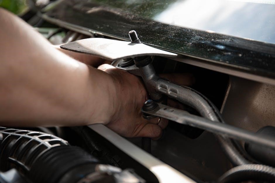
Outdoor Unit Installation

Carefully consider mounting location, ensuring adequate space and airflow․ Follow the mounting procedure precisely, securing the unit firmly․ Install the wind baffle for operation between 0F and 115F․
Mounting Location Considerations
Selecting the appropriate mounting location is crucial for the efficient and reliable operation of the TRUZA0121KA70NA outdoor unit․ Ensure the chosen location can adequately support the unit’s weight, considering potential snow or ice accumulation․ Allow sufficient clearance around the unit for proper airflow – a minimum of 18 inches on all sides is recommended, and more may be necessary in areas prone to heavy snowfall․
Avoid locations exposed to direct sunlight for extended periods, as this can reduce cooling efficiency․ Also, steer clear of areas where strong winds could obstruct airflow or deposit debris․ The unit should be installed on a stable, level surface to minimize vibration and noise․
Furthermore, consider accessibility for future maintenance and servicing․ Ensure there is enough space for technicians to safely access all components․ Avoid mounting the unit near combustible materials or sources of ignition․ Finally, check local regulations and building codes for any specific requirements regarding outdoor unit placement․
Mounting Procedure
Before commencing the mounting procedure, verify the mounting surface is level and capable of supporting the TRUZA0121KA70NA’s weight․ Begin by securely attaching the mounting bracket to the chosen surface using appropriate anchors and fasteners, ensuring they are rated for outdoor use․ Carefully lift the outdoor unit onto the bracket, aligning the unit’s base with the bracket’s supports․
Secure the unit to the bracket using the provided bolts and washers, tightening them firmly but avoiding over-tightening․ Double-check that all bolts are securely fastened and that the unit is stable and level․ Inspect the rubber grommets or vibration isolators to ensure they are properly positioned between the unit and the bracket to minimize noise and vibration transmission․

Finally, confirm that all clearances around the unit are maintained as specified in the ‘Mounting Location Considerations’ section․ A properly mounted unit is essential for optimal performance and longevity․
Wind Baffle Installation (0F ⏤ 115F Operation)
For operation within the 0°F to 115°F range, installing the wind baffle is crucial for preventing thermistor errors and ensuring consistent heating performance․ Refer to the separate wind baffle documentation for detailed installation instructions specific to the baffle model․ The baffle is designed to protect the unit’s sensors from direct wind exposure, which can cause inaccurate temperature readings․
Typically, installation involves attaching the baffle to the front of the outdoor unit using the provided hardware․ Ensure the baffle is securely fastened and doesn’t obstruct airflow excessively․ The system is engineered to cut out in heating mode if thermistor errors occur, automatically restarting once temperatures stabilize․
Proper baffle installation is vital for reliable operation in extreme weather conditions․ Always consult the dedicated wind baffle documentation for the most accurate and up-to-date guidance․

Refrigerant Piping Connection
Proper refrigerant piping is essential for system performance․ Adhere to specified piping size and length limitations detailed in the manual to maintain efficiency and reliability․
Piping Size and Length Limitations
Maintaining optimal refrigerant flow is crucial for the TRUZA0121KA70NA’s performance․ The installation manual meticulously outlines specific piping size and length limitations that must be adhered to during installation․ Exceeding these limits can significantly reduce system efficiency, potentially leading to compressor damage or unreliable operation․
Generally, the manual will detail acceptable liquid line and suction line diameters based on the total equivalent piping length․ Longer refrigerant lines require larger pipe diameters to minimize pressure drop and ensure adequate refrigerant delivery to the indoor unit․ The manual will likely provide charts or tables specifying these requirements․
Furthermore, the total equivalent length calculation considers not only the straight pipe runs but also the resistance added by bends, elbows, and other fittings․ Accurate calculation of equivalent length is vital․ Improperly sized or excessively long piping can compromise the system’s ability to reach its rated capacity and may void the warranty․ Always consult the manual for precise specifications related to your specific installation scenario․
Connection Procedure
The refrigerant piping connection for the TRUZA0121KA70NA demands meticulous attention to detail to ensure a leak-free and efficient system․ Begin by carefully deburring the pipe ends to prevent damage to the flare fittings․ Apply a refrigerant-grade sealant specifically designed for HVAC systems to the flare nut connections․
Tighten the flare nuts to the manufacturer’s specified torque using a calibrated torque wrench․ Over-tightening can damage the fittings, while under-tightening risks leaks․ Following proper tightening procedures is paramount․ After connecting the piping, a nitrogen pressure test is essential to verify the integrity of all connections․
Maintain the nitrogen pressure for a minimum of 24 hours, checking for any pressure drop․ If a leak is detected, immediately rectify it before proceeding․ Evacuate the system with a vacuum pump to remove any air or moisture, achieving the required vacuum level as specified in the installation manual․ Finally, charge the system with the correct type and amount of refrigerant, R410A, as indicated on the unit’s nameplate․

Electrical Wiring
Refer to the detailed wiring diagram provided within this manual for the TRUZA0121KA70NA; Always adhere to local and national electrical codes during installation and grounding․
Wiring Diagram
The TRUZA0121KA70NA wiring diagram is crucial for correct and safe electrical connection․ It illustrates the specific wiring configurations required for various voltage levels and control systems․ Carefully review the diagram before commencing any electrical work, ensuring a complete understanding of each connection point․
The diagram details the power supply connections, control wiring for thermostats and other external devices, and the necessary grounding procedures․ Pay close attention to wire sizes and color coding as specified in the diagram to prevent electrical hazards and ensure optimal system performance․ Incorrect wiring can lead to system malfunction, damage to components, or even pose a safety risk․
Furthermore, the diagram will indicate any required fuses or circuit breakers for protecting the unit․ Always use the specified ratings to safeguard against overcurrents․ If you are unfamiliar with electrical wiring, it is strongly recommended to consult a qualified and licensed electrician for assistance․ Proper wiring is fundamental to the reliable and efficient operation of the TRUZA0121KA70NA․
Grounding Instructions
Proper grounding is paramount for the safe and reliable operation of the TRUZA0121KA70NA outdoor unit․ Grounding provides a path for fault current to flow, minimizing the risk of electric shock and protecting the unit from damage․ Always adhere to local electrical codes and regulations when implementing grounding procedures․
The unit must be connected to a dedicated grounding electrode system, such as a grounding rod or a metal water pipe․ Use appropriately sized grounding conductors as specified in the wiring diagram and local codes․ Ensure the grounding connection is secure and free from corrosion․ A loose or corroded connection can compromise the effectiveness of the grounding system․
Never use gas pipes as grounding electrodes․ Regularly inspect the grounding connection to verify its integrity․ If you are unsure about any aspect of the grounding process, consult a qualified and licensed electrician․ Incorrect grounding can create a serious safety hazard and void the warranty․ Prioritize safety and follow all instructions meticulously․